
I was searching for a project to build a Z80 computer which could support an operating system such as some form of DOS or perhaps CP/M. I found Spencer’s RC2014 page at:
RC2014 website by Spencer Owen. (Semachthemonkey)
This website is a good basis for getting to know the RC2014 type of Z80 computer created by Spencer Owen and understanding what the concept of the RC2014 is. The RC2014 can be built with different modules which together can form a computer. Depending on what the user wants to do with the computer it can be composed of more or less modules. In the original concept the computer is completely split up into separate parts:
- CPU module
- ROM module
- RAM module
- clock generator module
- serial communications module
There are further modules which support a more complex computer, for example:
- compactflash interface module
- IDE harddisk interface module
- floppy drive interface module
- terminal I/O module
- bank switched ROM/RAM module
- video output module
- keyboard input module
- joystick input module
- sound output module
In the past I also saw some CP/M computers which had a serial port for keyboard input and screen output. Since I felt that the performance via a serial terminal would be limited I didn’t follow up on those ideas. But after further reading on Spencer’s website I found that such a serial terminal approach should not be seen as a limiting factor but rather as a useful addition which allows easy keyboard interfacing and a simple screen capability which might also be used for debugging purposes in certain cases. Especially when writing new code to support hardware additions or additional software functions. So after realising this I decided that a ROMWBW supported Z80 system would be very suitable as a schematic basis for my project. It’s fun to build a computer and expand it by adding more and more capabilities.
Z80-PC project (nov 2020)
I should start by mentioning that the RC2014 concept was invented by Spencer Owen. A big online community developed around it as you can find with just a little googling. CP/M is very important for the RC2014 and was inspired by modifications made by Grant Searle, a well known computer hobbyist. On his website you can also find a small CP/M computer which is a very attractive concept. It’s clear that the RC2014 fills a need for many users to get hands-on experience with a computer with a particularly easy access threshold. Also, the RC2014 has proven a particularly flexible and open concept, and is therefore very suitable for all sorts of expansions. Everything can be observed and measured directly on through-hole DIP ICs, rather than being locked up inside large scale integrated SMD ICs. This has definately inspired me to want to build this Z80 PC!
ROMWBW
Using Wayne Warthen’s ROMWBW software and hardware which supports a ROMWBW ROM, it becomes relatively easy to load software into the Z80 PC. There are many contributors supported by ROMWBW software from whom I have gotten inspirations and schematic ideas to start from. Sometimes they made their own versions of previously existing interfaces with their own useful additions. In the interest of easy reading I will include their names in square brackets, and at the bottom of this blog I will try to assemble a source web page list where you can find all their respective websites. If I have forgotton to mention anyone, it’s purely unintentional and I apologize beforehand if this would be the case! Just send me a note and I will gladly credit you accordingly.
I’m doing this project with and for my daughter who is now 10 years old. In the initial phase she has already helped me a lot with the soldering work for the prototypes. Later on we will do many coding collaborations and we have plans to port and develop games on the machine(we are huge fans of SNES Super Ghouls & Ghosts which was brilliantly made by Capcom), as well as doing some interfacing coding for VGA output control(initially through ISA PC cards), music ICs(Yamaha and others) and various other additions. What form the computer will finally get is fluid for us, it will definately be a kind of evolution which will be described on this blog page. The final result will definately be a larger PCB, probably in micro-ATX size, with additional expansion slots for further experimentation and coding. In this initial phase, our additions will be small in order to safely first reproduce the concept. Later on there will be larger additions and modifications planned.
To be clear: this is a hobby and non-commercial project, and nothing may be used commercially. As you can see from the many credits the schematics and designs are by many people and may not be abused in any shape or fashion. See their respective websites about their terms and conditions of use, required reading!
We have separated the Z80-PC project into PCBs which group things together logically with similar or related functions, as follows:
1. Z80 CPU Module [Karl Brokstad, Karlab]
– Z80 7.3728Mhz
– clock generators 7.3728Mhz and 20Mhz
– reset switch
– CPU signal LEDs (/M1, ACIA, /HALT, /INT, /NMI)
– 68B50 serial port TTL + RS232 I/O port: A0-A7 clocked at 7.3728Mhz [Karl Brokstad, Karlab]
2. ROMWBW compatible module [Wayne Warthen][Karl Brokstad, Karlab]
– 512 KB bank switched ROM file used: RCZ80_std.rom, currently with ROMWBW v2.9.1
– 512 KB bank switched RAM
– ROM(RED)/RAM(GREEN) and “bankswitching active”(BLUE) LEDs
bank control I/O port: 70-7F
3. Drive controller module
– Compactflash interface [Spencer Owen][Karl Brokstad, Karlab]
– 8255 IDE interface [Spencer Owen]
– Floppy drive controller [Scott Baker]
– CF and IDE activity LEDs
4. Terminal and composite video module
– VGA/USB keyboard Terminal with propeller mpu [Marco Maccaferri]
– TMS 9918 composite video display processor [J.B. Langston]
The 4 PCBs are 8x12cm and look like this:
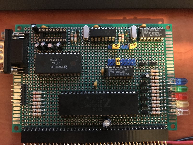
- CPU PCB:
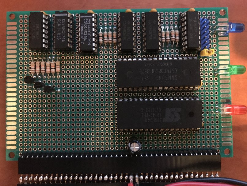
2.: ROMWBW PCB
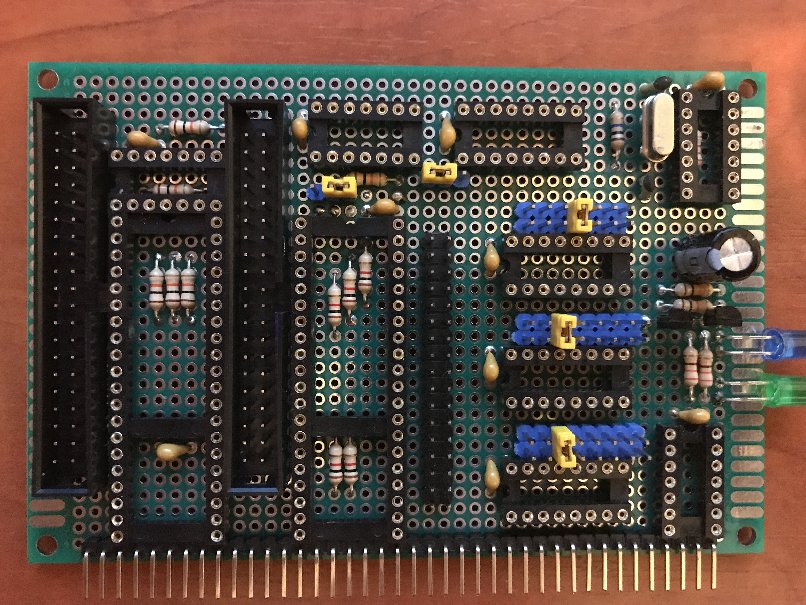
3. Drive controller PCB:
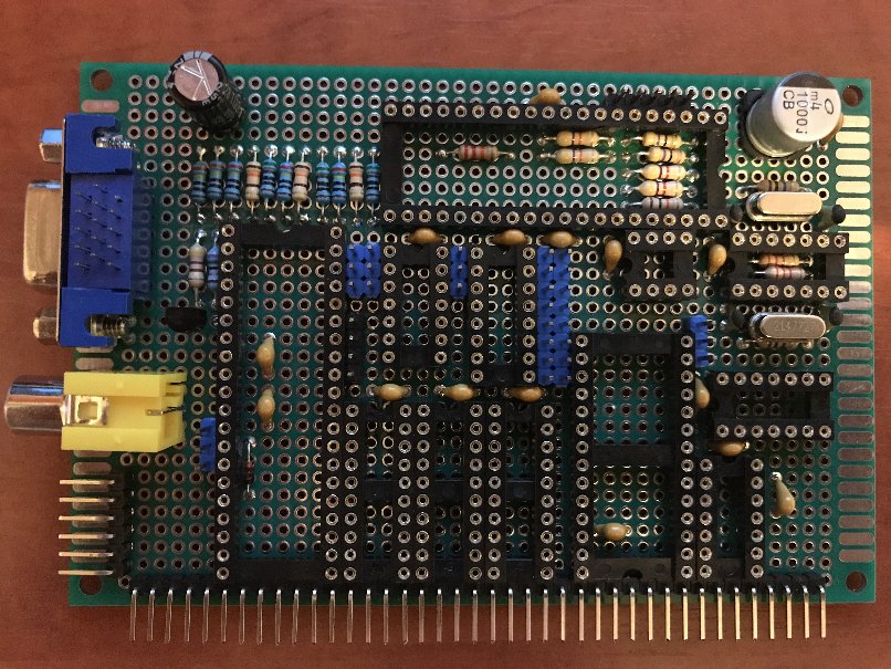
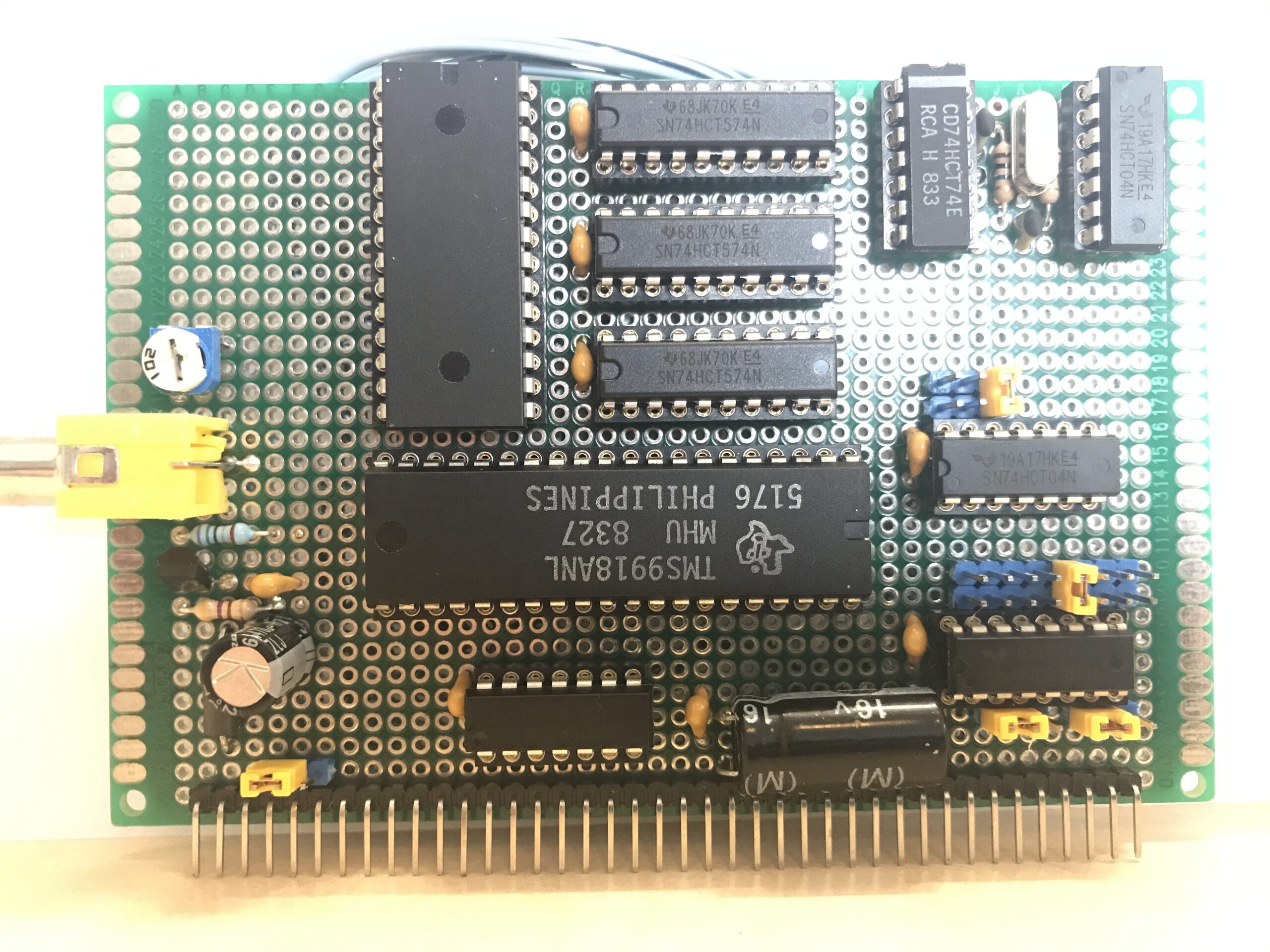
4. VGA and USB Terminal and TMS9918 Composite video output PCB:
The CPU module and ROMWBW module are now verified to be working as per the schematics.
There was some problem with the MAX232 IC which was cooking, never mind, I just unplugged it for now and will debug on breadboard later or choose another level shifter. Whichever will be better and easier. Just using TTL is fine for the moment though I would prefer a solid D-connector later.
There was also some problem with the ROMWBW ROM image v3.0.1 which somehow influenced my serial console output(!), which was not working. After suspecting a software problem and switching to an earlier ROMWBW ROM image v2.9.1 the problem disappeared.(!) I will investigate further now I know the cause. It is probably related to configuration or detection of the ACIA.
- ACIA is at port A0h for the moment (ROMWBW 2.9.1), in later versions it will be 80h.
- 115200, none, 8, 1, none setting for the connected terminal
- ROMWBW port range: 70h – 7Fh
- RCZ80_std.rom file flashed into the SST39SF040 ROM
- CLK disconnected from the bus for the moment
During my debugging work I just “piggybacked” the CPU and ROM/RAM boards with two female pinheader strips soldered together just to eliminate any HF problems due to my stripboard “backplane”. Next I will move back to the stripboard.
The CPU board and ROM/RAM board plugged together into two pinheader strips look like this:
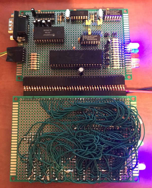
At the bottom you can see my laborious prototype wire soldering 😉
The wiring is looped a lot to be able to access all the pads even when wires are running across and around them.
I think it may be 10 meters of wire you are looking at…
This method has advantages:
- flexible
- faster result than ordering from PCB company
- cheap
and disadvantages:
- a lot of work!
- tight space for soldering requires some creative placement of looped wires
- difficult soldering iron positioning to get to the pads
- can only be reliable with a lot of careful considerations about how you do it!
- doesn’t look very tidy (only for prototype purpose)
After powering up only the CPU and ROM/RAM board or a similar configuration of your own together and connecting to a PC, putty serial port, 115200, none, 8, 1, none, you should be seeing the following screen appear:
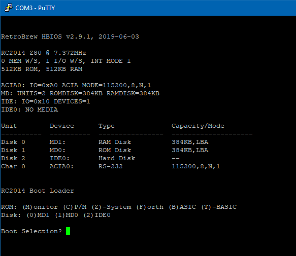
When this screen is showing it’s a good indication and proof that you have a working ROMWBW based computer.
With the ROMWBW LEDS it can be observed that first the ROM is active, then bankswitching becomes active and RAM is also active. During operation RAM and ROM are both showing LED activity.
As you can see, the ROMWBW RetroBrew HBIOS v2.9.1 creates:
- RAM Disk 384kb
- ROM Disk 384kb
- ACIA serial Character output and input data flow with the serial terminal
All without any external storage devices and without a CF card, just from the ROM.
With this setup you can already use:
- BASIC
- CPM
- FORTH
- Z80 Assembly Monitor?
After typing the menu letter as listed, the chosen item will be immediately loaded.
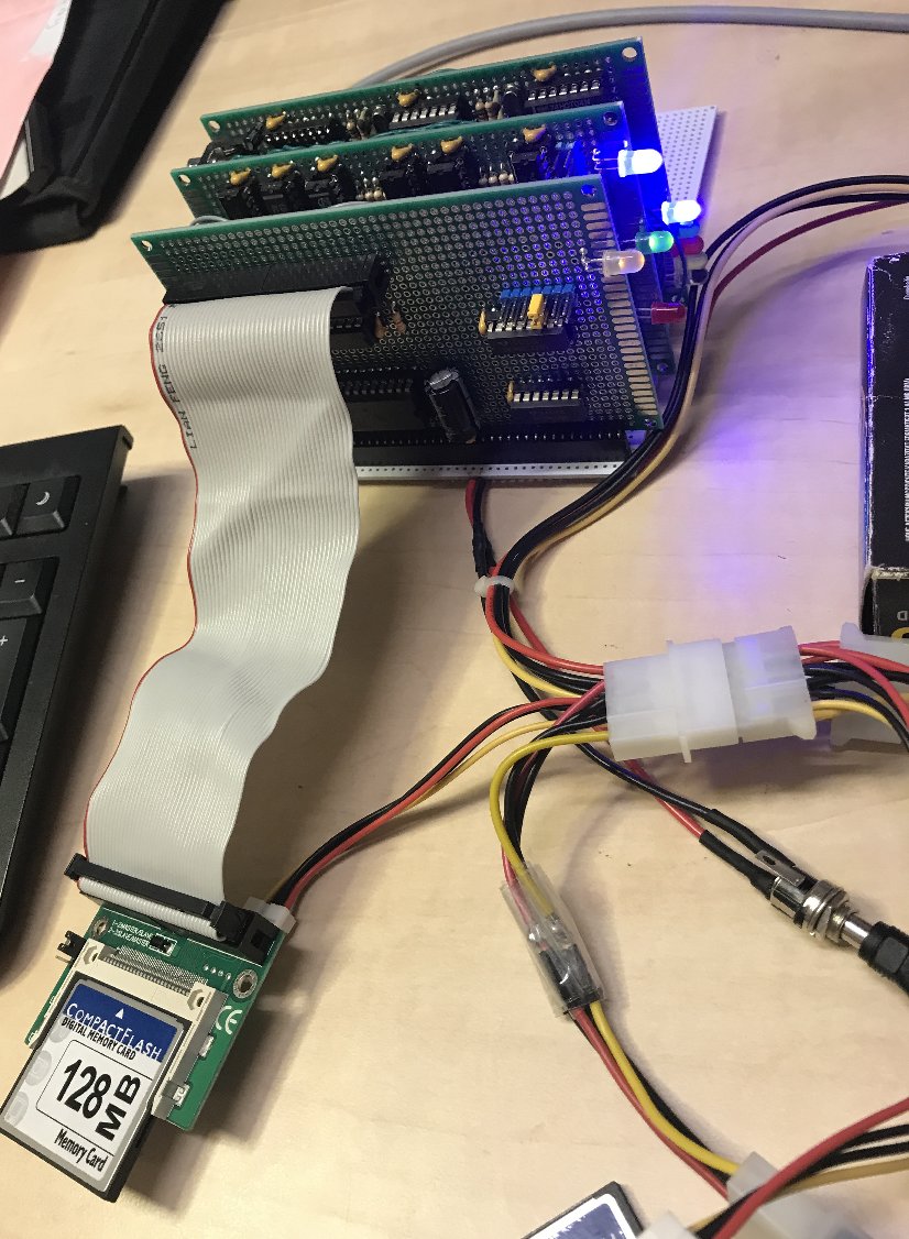
3. Drive controller PCB
After building and testing this combined PCB, it served to give me some experience with the properties of the interfaces which were included.
I found that particularly to connect the compactflash using the simplest IDE interface connection, which means to plug the compactflash card directly into the databus, caused a lot of instability in my setup. I am sure that has it’s reasons, but it did serve to demonstrate that the PPIDE method, to put a parallel port IC between the drive and the Z80 bus, is a far more stable and elegant approach. This keeps the signal on the Z80 data bus much more stable, which communication with IDE devices arrives on the parallel port IC instead. So I have decided that for now I will leave the “direct” IDE interface out in the future.
Additionally, I was having some problems with the floppy drive controller, so I decided to rebuild the floppy drive controller and PPIDE on separate PCBS.
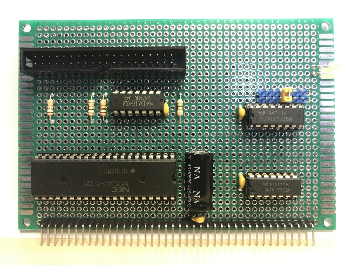
PPIDE Interface
I have moved the PPIDE interface on a separate PCB project, and after building it, I also started to use the dev branch source code of ROMWBW for building a ROMWBW ROM image, which allows for easy customization of the driver loading process, and adding some custom options to the drivers when needed. Additionally, the drivers which I don’t need can be left out in the custom ROM which is built from the sources. After testing the PPIDE interface, I got some more experience with reserving CPM disk slices on the CF card, adding a FAT compatible partition after the area used by the disk slices. Also I got some experience formatting the disk slices and making them bootable. The FDISK manual in the Doc directory provides all the information to guide this process! I used the partitioning method on the CF card, and also on a regular mechanical laptop IDE harddisk. I used some adapter PCBs for both cases because I used an IDE connector on my board.
Floppy drive controller RCWDC
After building and testing the PPIDE, I moved on to rebuilding the floppy drive controller on a separate PCB. I had some initial problems to get the interface detected by the ROMWBW software, but after adding a debug code thanks to Wayne Warthen, I discovered some instability in the detection bytes, which after exchanging a 74HC125 IC for an LS type finally was solved. After that the experience was very smooth! I have formatted some floppy disks and made them bootable for CP/M. Everything was working according to the descriptions I read!
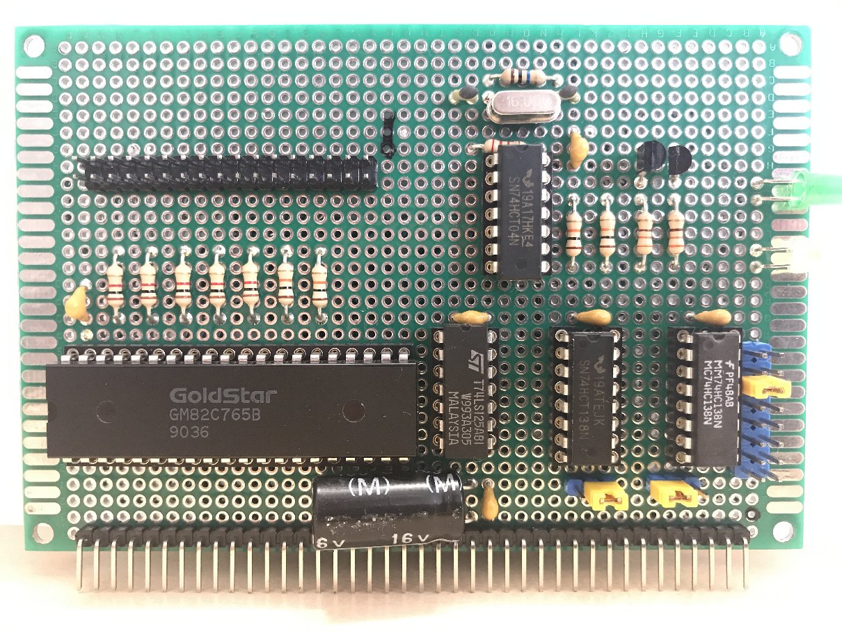
In the photo above you can see a GoldStar brand FDC controller chip which I have desoldered from my old 286 AT PC. I was still in the phase where I didn’t know what the cause of my problems was, and used that ISA floppy adapter to test my controller ICs. Thankfully my newer LGS branded chip was also in working condition in the PC! I left the older GoldStar chip on this PCB, it seemed more retro looking!
4. Video output for the Z80-PC – TMS9918 and VT82C42 PCBs
In order to get an actual console video output and graphics screen for the Z80-PC, I decided to also move the TMS9918 project on a separate PCB. And I am glad I did, because the video RAM and the 3 gates to interface with it needed many wires! It still got cramped on the back of the PCB! I got a good display on my first attempt, and switching the ROMWBW console to the TMS composite output was also working right away!
I did find that I lost keyboard control after switching the console from the putty serial connection to the TMS composite output. That is because video and keyboard are combined devices in the driver model of ROMWBW.
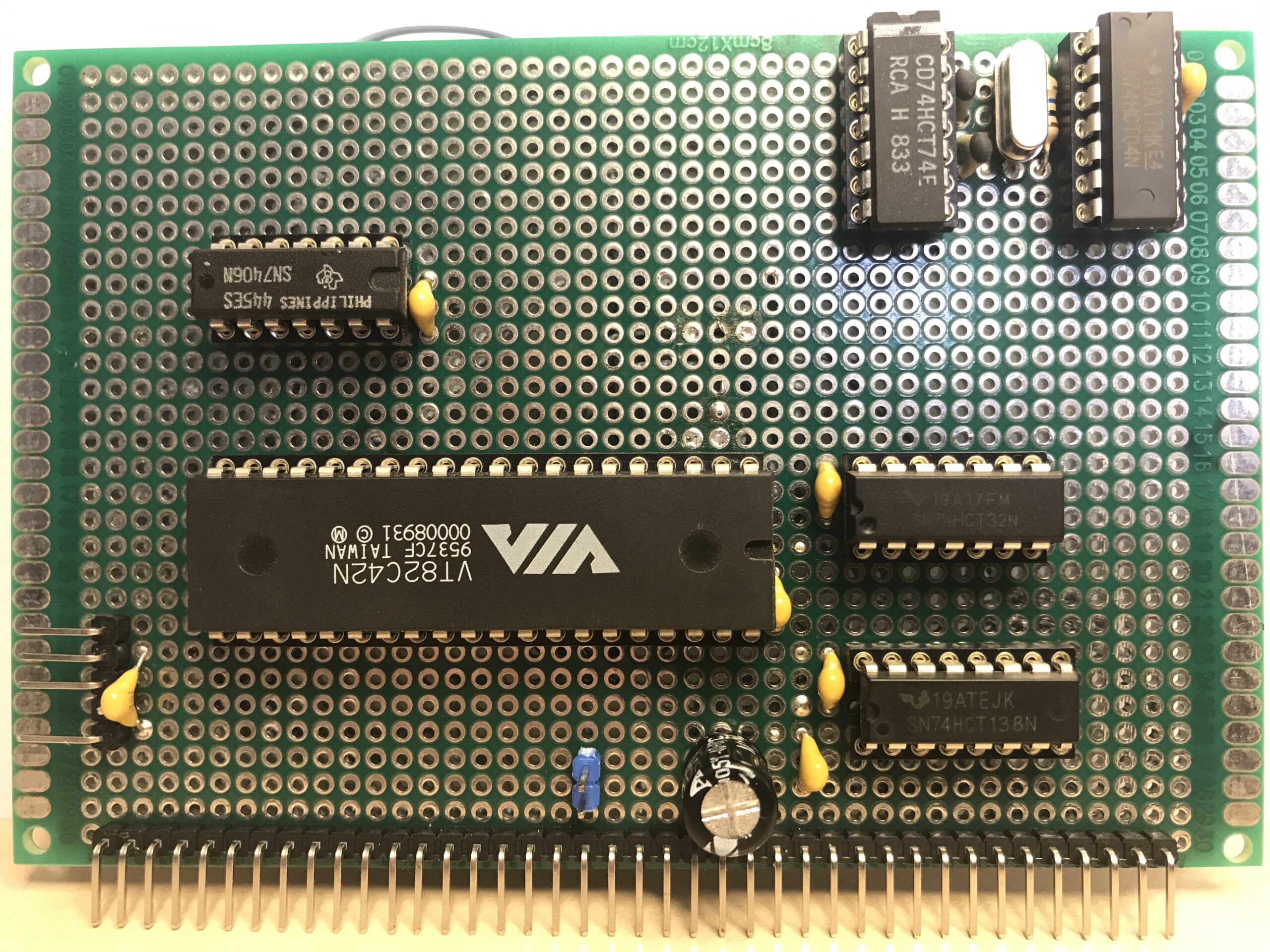
I discussed the matter with Wayne Warthen, who created ROMWBW. The solution we came up with was that I design and build a VT8242 keyboard controller PCB to be able to combine that as a console keyboard in the TMS video driver, and Wayne combined it as a separate option when activating the TMS driver in a configured ROMWBW build from the sources. He was very kind and helpful to write some extra code lines in the dev branch github source code of ROMWBW to support the new configuration which I needed. After building this ROM, everything worked straight away! I did disable INT control by removing a jumper I included, which was necessary because the keyboard driver does not use interrupts. I had already accounted for this possibility. The ROM boot messages nicely showed the keyboard driver and port number!
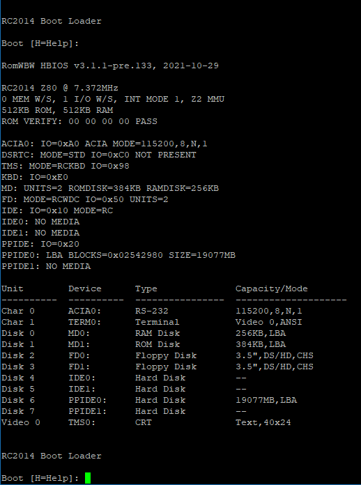
The putty boot messages show the current included hardware in the Z80-PC