
The ZX Spectrum Issue 7 is my version of Mike Wynne’s ‘Speccybob’, an excellent project which is basically a ZX Spectrum computer without any custom chips, made with conventional logic ICs which means that anyone with reasonable electronics skill, precision and patience can build their own ZX Spectrum now.
Issue 7
Why did I choose the name Issue 7? It’s simple. Sinclair made a lot of revisions for the original ZX Spectrum computer. It ranged from Issue one until Issue 6a. My design is called Issue 7 because it is designed to fit inside an original ZX Spectrum case. For some people this might be good news because I am sure there are quite some ZX Spectrums around which are for some reason defective, such as for example because of onboard power supply circuit failure, Ferranti ULA custom chip failure due to overheating and extended use, memory faults, etc. A keen hobbyist can now build a high quality replacement board for their Spectrum ( or ‘Speccy’:).
Some details about the design
I tried to keep the measurements and details of the Spectrum Issue 7 PCB as closely to the original spectrum PCB as I could. However there are a few things to observe:
– scale of printout on your transparent sheet: make sure your printed layout is the correct scale. Some laser printers are not very precise so you might need to experiment with a few printouts. (use the % scale setting of your printer driver options to get it right) measure the exact center distance between your spectrum’s PCB support holes on the lower shell of your spectrum housing, then compare it to the distance between the Spectrum Issue 7 PCB printout sheet’s PCB holes. That way you can know if the PCB will fit reasonably. Of course there can be some tolerance in these matters, it does not need to be terribly exact in order to fit. A millimeter or two deviation can still be made to fit with the help of a small round file, I just want to make you aware of the fact that the printout might vary on different printers, something that otherwise might be overlooked.
– the connectors: some changes were made compared to previous spectrum PCBs. The video output connector no longer carries a modulated TV frequency output, instead I have chosen for a DB9 female PCB connector which is placed near to the original Cinch connector where the modulator used to be. This connector gives us seperate RGB signals, as well as composite, horizontal and vertical sync signals. Picture on the monitor will be much clearer with these outputs. The difference in connector shape requires you to enlarge the original connector hole to accommodate this connector. If you don’t want to do this, you could optionally choose not to implement the DB9 connector on your PCB and solder a cable directly into the PCB. In my opinion it is the best solution to use this DB9 connector on the PCB. My advice is, be exact, do a lot of in-between-fitting while gradually cutting out the hole. Best way is to use a file to enlarge the last few millimeters so it is a good and neat fit. First the lower shell, until the PCB can fit to it with the connector soldered onboard. Take your time, so it will be a satisfactory result afterwards.
As for the expansion connector, you should be aware of a few things. It is not a ‘wobble’ 😉 edge connector as in the original speccy, I chose for a flatcable boxheader. The advantage is a tight fitting, reliable and flexible connection using a flatcable. The connector does not match the original Spectrum contact order, so if anyone wants to add an original Spectrum expansion, they will need to convert the pin order accordingly. This could be done with a small conversion PCB which carries the original edge contacts, or perhaps by soldering flatcable wires directly on the spectrum expansion. The expansion connector of the Spectrum Issue 7 exactly matches the Z80 CPU’s pins, with the extra signals added at the end, same as the Micro-ZX81 PCB. I want to create a ‘kind of’ standard since the Micro-ZX81. When I made the layout, this connector made it as easy as putting it next to the Z80 and adding all the parallel traces. This saves considerable board space. Have a look at the euro-ZX81 CPU Board to compare. Another advantage in the future might be to have some ‘cross platform’ expansions. I feel it would be great to have some general Sinclair ZX expansions which can be used by ZX81 users as well as by Spectrum users. This might save me some design work as well in the future, doubling the usefullness of any future expansions. If this indeed will be the case, we will have to wait and see.
As for the some other outside connectors: I chose to keep the same shapes as the original connectors used by Sinclair. The idea would be to desolder them from the original PCB and solder them into the Issue 7 PCB. An alternative would be finding some original connectors which fit correctly.
The internal keyboard connectors: these are not in the same locations as the original layouts, because the current locations made the PCB design easier. This will not be a problem because the contacts from the upper shell’s keyswitch need to be properly secured anyway. It will be best to use the original keyswitch connectors, solder a flatcable of sufficient length to it, shorten the keyswitch in such a way that you can insert it into the soldered keyswitch connector and carefully superglue this assembly onto a suitable spot on the upper shell. I plan to make some photos of my own modification inside my original rubber keyed Spectrum. As soon as I have them I will add them to this page. Anyway, after modifying the keyswitch into flexible and stable flatcables and using some precision IC-socket connectors as I use with all my designs, it will be easy to connect the keyboard.
Also see the Partslist and Schematic below for some more details about the connectors and their functions.
A screenshot of the CAD drawing which can give an impression of the density of this project
A few facts about this board:
Total number of pins: 1045
Total pins with connections: 925
Total number of via’s: 373
Total number of connections: 717
Number of ICs: 47
That means that the board has 1418 holes in it…. 🙂
Current Project Status:
The PCB layout is fully finished, ground and VCC areas have been recreated in CAD.
The finished layout is etched now, all the holes are already drilled. Next job is to solder in all via wires and use a magnifying glass to carefully study the etched PCB for any errors with a TL light source below and above the PCB. If there are any errors these can be corrected by soldering. It’s always easier to study carefully before testing than to find the connection fault after all the parts are soldered in. I can recommend taking some time for this.
Here are some pics of the PCB, here not yet drilled:
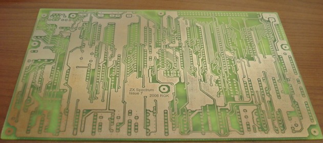
ZX Spectrum Issue 7 – top layer (just etched and stripped)
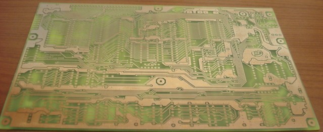
ZX Spectrum Issue 7 – bottom layer (just etched and stripped)
As you can see, the PCB was slightly over etched in the power planes, but the copper is still a solid surface so it’s fine. I tried to match the case holes with the original Spectrum PCB. Some small filing might become necessary for a complete fit. Also note that I have manually edited in all the power planes and enlarged the pads for the connectors because they need large holes.
Next phase: soldering in the via’s, carefully checking the PCB traces. Sometimes a little local flux cleaning is needed to make sure there are no short circuits.
Please note: this design has already been built and proven by some users who requested my PCB designs for it.
ZX Spectrum Issue 7 Schematic
ZX Spectrum Issue 7 Component Placement
ZX Spectrum Issue 7 Partslist
U1 – Z80A CPU
U2 – 27C256
U3 – 62256
U4 – 74HC374
U5-U8 – 74HC245
U9-U10 – 74HC574
U11-U12 – 74HC153
U13 – 74HC166
U16-U17 – 74HC4040
U18 – 74HC245
U19-U20 – 74HC157
U21 – 74HC245
U22 – 62256
U23-U28 – 74HC161
U29-U32 – 74HC85
U33 – 74HC138
U34 – 74HC4040
U35 – 74HC164
U36 – 74HC138
U37-U38 – 74HC74
U39-U40 – 74HC73
U41 – 74HC20
U42 – 74HC86
U43 – 74HC08
U44-U45 – 74HC32
U46 – 74HC08
U47 – 74HC00
U48 – 74HC27
U49 – 74HC04
C1 – 1uF
C2-C4 – need testing with tape
C5 – 100pF
C6 – 100uF
C7-C20 – 100nF
R19 – 2k2
R20-R21 – 470 ohms
R22-R26 – need testing with tape
R27-R28 – 100k
R29-R30 – 470 ohms
R31 – 4k7
R32-R34 – 470 ohms
R35-R37 – 150 ohms
R38 – 2k2
R39-R40 – 4k7
P1 – 10k
RN1 – 10k 8res 1com
RN2-RN3 – 4k7 5res 1com
X1 – 14Mhz xtal
J – 50 pin FC boxheader
JPWR – power connector
J1 – 2pin sil header
J2 – 5pin sil header
J3-J4 – 3.5mm jack connector
J5 – 2pin sil header
J6 – 8pin sil header
J8 – 9 pin sub-d horizontal female
Some advice:
I designed the PCB to accommodate the original MIC,EAR and Power connectors as found on the original spectrum board. The idea is to solder them out and move them to this PCB. A small catch: the signal connections of the MIC and EAR as well as the power connections of the Power connections are also routed to the top layer of the PCB. However when the PCB is etched at home, we can’t have metallised holes. I would advise to carefully solder a wire inside the hole of these pads, make sure the wire is soldered to the top layer pad, then put the connector into the board and solder the bottom connection together with the wire you put in already. Another way to do it is drill a tiny hole(0.6mm) inside or right next to the pad, and solder in a wire to make the top to bottom connections needed. In both solutions it would be wise not to keep the soldering iron on the bottom connection for too long or else the top soldering of the wire might get loose. Another idea would be to carefully try to solder the legs of the connectors also to the top layer pads if you can reach them. This is my preferred solution but depends on if you can reach them.
J – Expansion port (not same connection order as original spectrum!)
JPWR – Power connector – Please note! The power connector needs a stabilized(!) 5V DC power supply. My advice is to either buy a 5V power adapter (small switching mode power supply) or make your own one with a transformer, rectifyer, 7805 which can carry a good current and several capacitors for stabilazing. I purposely didn’t include any power supply onboard for several reasons, it saves space, but also more important: it reduces heat production inside the Spectrum case which we don’t want because it will make the keyswitch foil dry out.
J1 – Reset switch connection
J2 – keyboard connector
J3 – MIC
J4 – EAR
J5 – Speaker connection
J6 – keyboard connector
J8 – video connector:
1 – red
2 – green
3 – blue
4 – gnd
6 – horizontal sync
7 – vertical sync
8 – composite sync
Its best to use a 9 pin female horizontal Sub-D connector and, as described before, to carefully work on the housing to make a precise hole which can accommodate the connector’s necessary space. After that you will need to make your own custom cable to connect to your TV’s scart or other RGB/Sync connection.
Please see the Building Tips to see some photos of how I modified the original Spectrum housing in order to first preserve the very delicate keyswitch foil of the original Spectrum(which is over 20 years old!), as well as make a steady and secure connection by using the original keyboard headers to connect to them with pre-soldered wires.
The copyrights of Sinclair Technology are the property of international computer manufacturer Amstrad. It is not allowed to use any designs provided in this website and/or any Sinclair Technology found elsewhere on the internet for any commercial use. It is not allowed to sell computers built with or based on plans from this website with the intent to make any commercial profit or gain. The sole purpose of the designs in this website is to use the designs for your hobby or for non-commercial learning purposes.